|
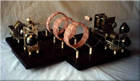
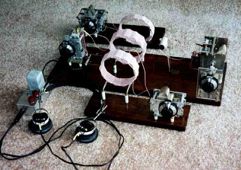
Lyonodyne Version 17 Crystal Set
Summary
The "Lyonodyne-17" is a much-advanced version in a
series
of DX crystal
sets evolving from circa 1974. I've been particularly interested
in crystal sets since 1959, when I first discovered you could actually
DX with them. It's a completely passive set -- no amps, no bias
on
the detector. The circuit is double-tuned and uses super-high
quality
components: silver-plated variable capacitors and high-Q litz
wire
basket-wound coils. Isolated coil Qs are in the 700s across the BCB and
over 1000 for much of the BCB. In-set Qs are less, of
course.
Phones are high quality, surplus sound powered ("balanced armature")
units,
matched to the high-Z secondary tank/detector by a high quality line
transformer.
Detector is a single 12101 3RT, sold by Radio Shack as a "1N34
Type."
It's the best I've found so far. With traps and all, it takes up
the better part of a desk top.
Description
After several abject experimental failures, I
concluded
that the
magical "high L-to-C ratio" for tuned circuits is a crock -- in spite
of
what theory might suggest. That, and the high Qs obtained in
200/44
litz wire (now, 660/46) coils got me to re-thinking my set's
design
and construction. This led to a completely rebuilt crystal set -- same
circuit, but redesigned components per the following principles:
(1) design for the lowest L/C ratio as
practical
(2) use highest quality variable
capacitors
available
(3) if necessary, pad the variable
capacitors
with high-quality
air trimmers to get to lowest frequency and spread out top-end tuning
(4) choose coil design which peaks in Q
in the
central
BCB range -- operating near the self-resonant frequency is
self-defeating
Superior quality tuning capacitors (silver plated
with
ceramic standoffs)
were used in the present version. The two prime tuning capacitor
candidates I had were a 500 pF and a dual, 470 pF per gang, both
silver-plate,
ceramic insulated. (Typical parallel leakage resistance
measurements
on these were 20 megohms, by the Boonton 260-A.) Accordingly, the
set was designed about them.
I credit Bill Bowers of Oklahoma with exposing me to
the
virtues
of finer-strand litz for medium frequencies, the use of larger coil
diameter-to-length
ratios (ca. 5-to-1) than theory suggests, and for going back to
'over-1,
under-1' winding pattern. They are not as pretty and have lower L's
than
the same-sized 'over-2, under-1's', which I used for many years, but
they
do have substantially higher Q's.
And credit to Al Klase for preaching the virtues of
sound-powered
phones long enough and loud enough that I finally had to listen --
despite
my being firmly convinced nothing could ever surpass Brush crystal
phones.
The sound-powered's are a real ear-opener, literally, and an
order-of-magnitude
improvement.
Antenna has been, for some time, a 50-foot, 4-wire
flat top
(wires
spaced 1 ft. apart), maybe 25 feet high. At my previous location,
I used to have a 105-ft. long-wire, but high winds took out the tree at
the other end. The shorter flat top worked so well I
brought
it here to Hawaii, where real estate for long antennas is at a
premium.
It's about all I can fit gracefully onto this lot. Ground is
tapped
directly into the city water system.
Circuit Details
The antenna-ground system is tuned by the primary,
L1-C1,
and is
coupled to the secondary, L2-C2, via loose L1 - L2 coupling (physical
distance
3 to 4"). L1 and L2 are positioned radially (side-to-side), while
the coils of two QRM traps (high-Q, parallel L-C ckts.) are coupled
axially
to L2. L1 has virtually no effect on L2-C2 tuning and Q, but the
QRM traps do affect tuning, especially near the QRM frequencies.
So, their coupling is kept to the minimum which will still allow
reception
of the stations of interest. The set is capable of receiving stations
on
frequencies adjacent to murderous locals. The low-Z sound-powered
phones are impedance-matched to the secondary tank , L2-C2, and
detector
with a UTC A-27 100 k-ohm-to-200 ohm input transformer. The
single12101
diode detector is estimated to present about 200 k-ohm resistance in
the
forward direction. These impedances, in series, allow you to
place
the detector-phones directly across the tuned circuit without undue
loading.
Taps, used in the past, are a mess -- especially with litz wire.
Further, they kill a coil's Q, and are to be avoided if at all possible.
|