|
The
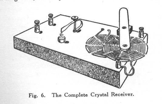
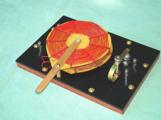
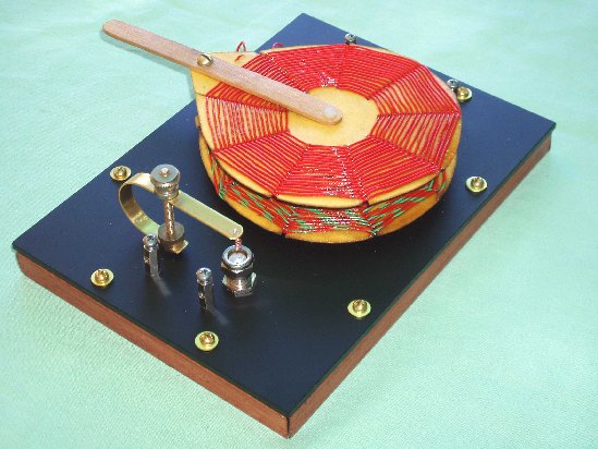
Variometer Crystal Set
This simple crystal set is described in ‘The Boy’s Book
of Wireless’ by Ernest H. Robinson, published by Cassell and Co. of
London in
1923.
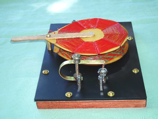
I have built this set following closely the instructions
and diagrams as set out by the author and have tried to make it look
authentic
by using materials similar to those available to a constructor in 1923.
It
would have been nice to wind the coils with cotton covered wire but it
is
difficult to find these days. Brass and nickel plate parts and an
‘Ebonite’ and
wooden base board give that antique look.
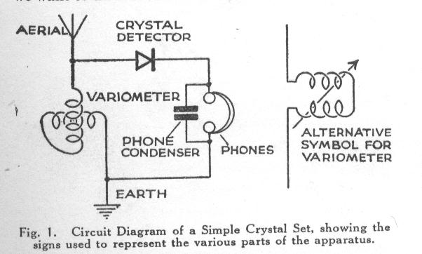
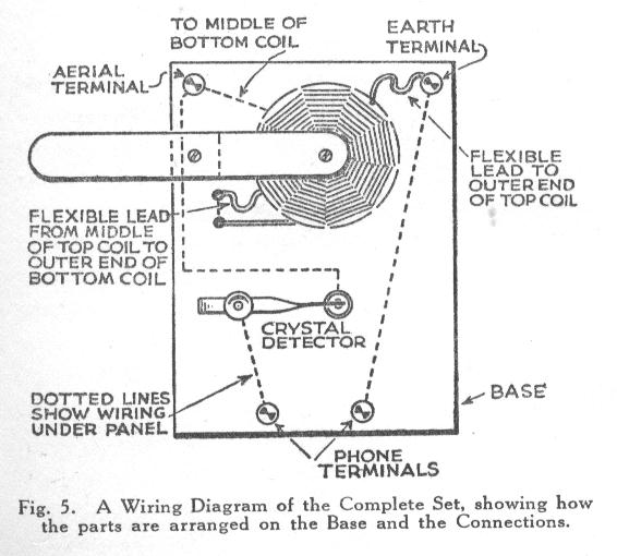
In the circuit diagram a 0.002 capacitor is shown
across
the headphones. The author suggests that this is optional and he leaves
it out
on the construction diagrams. I have found its inclusion makes no
difference to
the performance of the set as most magnetic headphones have ample self
capacity.
Using a variable inductor as the tuning element was
common in early crystal set designs as it avoided the purchase of an
expensive
variable capacitor but it did have some drawbacks. Selectivity is broad
and the
tuning range is restricted, not covering the entire broadcast band.
Remember
though that in 1923 even a large city such as London had only one
broadcast
station so adjacent channel interference was not a problem! The theory
of
operation is that the inductor acts as a loading coil to bring the
antenna to
resonance, so the ‘tuned circuit’ is the inductor plus the capacitance
of a
short (less than a quarter wavelength) antenna. Things would probably
not work
too well if the antenna was longer than a quarter wavelength and
inductive, but
that would mean an antenna length greater than 75 meters or 250 feet.
Construction Hints
I buy most of my hardware and
electronic bits and pieces
from an Australian outlet called Jaycar Electronics. They do a very
good mail
order service and stock nearly everything you could ever need. They
have a
website and catalog in US dollars. Check out http://www.jaycarelectronics.com
for the
online catalog and to look at the parts I mention and http://www.jaycarelectronics.com/catalog
to order a paper catalog .
Base Board
The base board is made from 3mm thick black acrylic
sheet
and measures about 125mm x 175mm. I found some acrylic which was glossy
on one
side but matte on the other. The matte side looks like the traditional
Ebonite
board used in early radio equipment. I get my acrylic from a factory
which
makes plastic advertising signs. They always have cheap off-cuts. A
12mm x 12mm
timber edging gives room under the base board for the wiring. A small
wooden
picture frame makes a ready made edging. Check out K-Mart or similar.
NOTE –
NEVER solder any connections to components while mounted on the acrylic
base
board – ACRYLIC WILL MELT! Use solder tags then bolt it all
together.(Jaycar
catalog number HP-1350)
Terminal Posts
I make these from nickel plated brass 10mm long
tapped
spacers (Jaycar catalog number HP-0900). These spacers are tapped
through with
a standard 3mm metric thread. Drill a 2mm hole through the side of the
spacer
about 5mm from one end such that a wire placed through the hole will be
held
firmly by a screw screwed in from the end of the spacer. Get some 3mm
screws to
fit. (Jaycar catalog number HP-0400)
For an
antique
look, remove the nickel plating with fine
sandpaper and polish up the underlying brass.
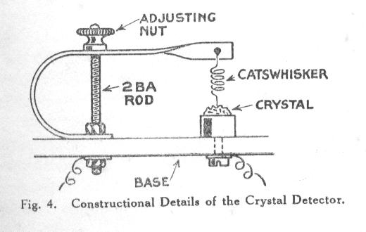
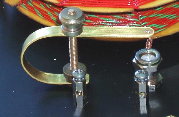
Cats Whisker Holder
The diagram explains the construction pretty well.
The
brass strip and threaded rod came from a hobby shop. The brass strip
measures
6mm wide by 0.6mm thick by 105mm long and was bent around a 25mm
diameter piece
of PVC pipe. The threaded rod is about 40mm long. The brass adjusting
nuts/knobs came from the tops of old dry cell telephone batteries. You
will
have to hunt through your junk box for something similar. The
catswhisker is
fine bare copper wire soldered in place.
Crystal Holder
The crystal holder is made from a cut down male and
female ‘F’ connector. This type of connector is used on RG-6 and RG-59
TV
coaxial cable. What you need here is an F59 screw on plug (male) and a
F61
chassis or wall plate socket (female).Have a look at the pictures in
the Jaycar
catalog. (Jaycar catalog numbers PP-0637 and PS-0645).
Start with the male plug. What we want from
here is the threaded coupling ring. Slip a small hacksaw blade behind
the
coupling ring and carefully cut the body of the plug in half. This will
allow
the ring to fall free. Now take the female socket and using a pair of
pliers,
pull out the connector pin from the back of the nylon center of the
socket.
Take twist drill that will fit into the front of the socket and drill a
shallow
hollow in the nylon center of the socket. Do not drill away any metal.
Fit a
suitably sized piece of crystal (Galena) into the front of the socket
that you
have just drilled out and secure it by screwing on the coupling ring
salvaged
from the male F connector plug. Mount the crystal holder through the
base board
and secure with the nut and washer supplied. A solder connection is
made to the
side of the washer before mounting. (otherwise you will melt the
acrylic base
board). By the way, there is a good description on this website about
how to
make Galena crystals using lead, sulphur and your mother’s best tea
spoons –
but don’t tell her. (See Fun Tips and Projects – page 2)
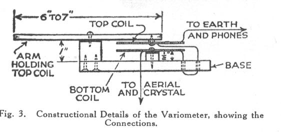
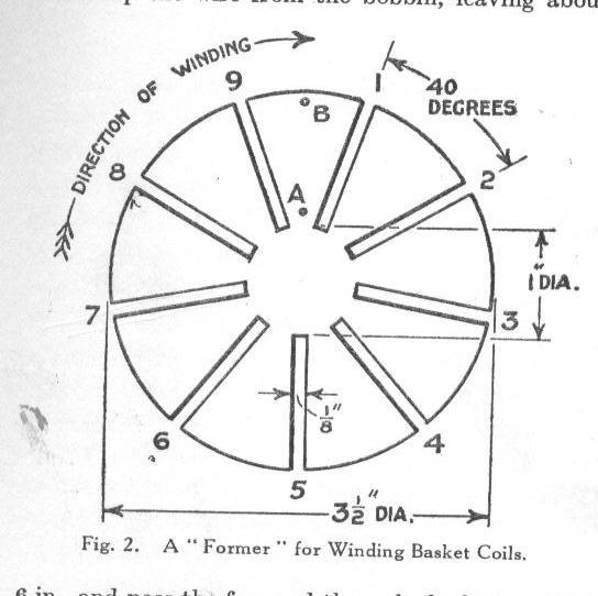
Spiderweb Coils
How to wind spiderweb coils is described elsewhere
on
this website. The diagram gives the dimensions of the cardboard formers
which
in this case are not removed when the coils are finished. Be careful
that both
coils are wound and mounted so that the wire turns go in the same
direction. I
wound 32 turns of plastic insulated wire on each of my coils, as much
as I
could get on the formers. Varnished winding wire will allow more turns. The original notes suggested 40 turns but the
exact number to tune the broadcast band will vary slightly depending on
the
length of the antenna you are using. This is because of the simplicity
of the
design where the antenna and the variometer coils form the tuned
circuit. Leave
plenty of lead length at the start and end of each winding to allow for
the
flexible connections. A coat of varnish
will help hold all the windings in place.
Performance
This set is no DX performer but is a simple design
for
close in domestic listening, selectivity is broad but local stations
peak up
nicely on 50 feet of antenna wire and a good water pipe earth. I have a
50KW
national broadcast station about 15Km (9 miles) away and when tuned in,
headphone volume is almost too loud. Tuning lower powered and more
distant stations
is possible but the 50KW is always there in the background.
Written and Photos by
John Hassell
VK6JAH

How a Variometer Works
A variometer is a device that uses two coils to
provide a
continuously variable inductance. If two coils are connected in series
and
spaced apart so that their magnetic fields do not interact, then the
total
value of inductance is simply the sum of the inductance of each coil.
If the coils are placed in a position where their
magnetic fields can interact then interesting things happen. The value
of the
total inductance is found to be either larger or smaller than the sum
of the
individual coil inductances, depending on the positioning of the coils
and
whether the wire turns are in the same or opposite directions.
(in-phase or
anti-phase). The amount of inductance that is gained or lost is due to
a
phenomenon called Mutual Inductance.
If the coils are placed in-phase (the windings of
both
coils go in the same direction) then inductance is gained. If the coils
are in
anti-phase (the windings go in opposite directions) then inductance is
lost
Let’s check out the spiderweb coils used in the
variometer crystal set. Using the formers as described and winding on
40 turns
of wire gives a coil measuring about 110uH on my inductance bridge.
Connecting them in series, with the end of the first
coil
connected to the beginning of the second coil and the coils well
separated,
total inductance is as expected around 220uH.
If the coils are
now carefully laid one on the other in-phase (both windings in the same
direction) the total inductance increases to about 400uH. That’s nearly
twice
the value of inductance we would expect from just adding the inductance
values
of both coils.
On moving the
coils apart the total inductance value will fall back to 220uH. In fact
any
inductance between 220uH and 400uH and be produced by careful
positioning of
the coils.
By reversing the connections to one coil (end of first
coil to end of second coil) or by just flipping the coil over puts it
in
anti-phase (windings in opposite directions). When one coil is laid on
the
other a decrease in total inductance to around 50uH is seen. Again,
moving the
coils apart will produce any value between 50uH and 220uH.
So here we have a way of smoothly tuning our crystal
set
by moving coils rather than using an expensive variable capacitor. But
there is
a problem. If you have built the variometer crystal set you will have
found
that the change in inductance is not enough to tune across the whole of
the
medium wave broadcast band. The way around this is to tune the bottom
of the
band with coils in-phase and switch to an anti-phase connection to tune
the top
of the band.
John Hassell
VK6JAH
jah12@bigpond.com
|