How A
Crystal Radio Works
In order to understand the crystal radio receiver you first have to
understand
were the "signal" or radio wave comes from and how it was made.
The
Transmitter
A radio station is allowed to broadcast a radio wave. The radio wave is
sort of
like dropping a pebble into a pond of water. The ripples or waves
radiate
outward from where the pebble was dropped in the water. Radio wave
radiate
outward from the radio stations antenna sort of like the waves in the
pond.
Radio waves are electromagnetic waves that travel through the air.
In our figure #1 below, we have a wave. The wave below shows one cycle.
How
"strong" a wave is we call its amplitude.
Figure#1
In
our second example in Figure #2, we have a radio wave that has cycled 3
times
in one second. This is called the "frequency" of the radio wave. In
this case the frequency is 3 cycles per second. We measure frequency
using the
term hertz or Hz which is the amount the radio wave cycles in one
second. The
term "hertz" came from the German physicist Heinrich Hertz, born on
Feb 22, 1857. It was named in his honor for the work he did with
radio
waves research.
So below in Figure #2 we have a radio wave with a frequency of 3 Hz (3
cycles
per second).
Figure
#2
The
AM radio band is from 530,000 Hz to 1,710,000 Hz. We use the
designation k
for 1000, so it would be written as 530 kHz to 1710 kHz.
The AM radio station can broadcast a radio wave on one frequency
between 530
kHz and 1710 kHz. The FCC regulates which frequency they can use.
Now for a sample radio station. It is "radio station 610 on the AM
dial". This means the radio station is broadcasting a radio wave of 610
kHz or as we now know, a radio wave that cycles 610,000 times a
seconds! That’s
correct, 610 thousand times each second!
OK, then how does that wave carry the sound?
The radio station has equipment that varies the "strength" or
"amplitude" of the radio wave (see Figure below). It still cycles at
the same rate, but it gets stronger or weaker according to the sound.
Figure #1 (again)
Notice
in Figure #3 below that both waves are cycling
at 2 cycles per second (2Hz), but the amplitude in wave B is much
higher than
in wave A.
 Figure #3
If
that amplitude is controlled by the sound say from a
microphone (with other equipment), going up and down but is cycled at a
fixed
rate a second, you have a radio wave like the type coming from a
radio
station! The station is "modulating" or varying the amplitude of the
radio wave. This is called "Amplitude Modulation" or AM.
In
Figure #3a below you will see a "modulated"
wave at 8 Hz (cycles per second) on the top example and a "modulated"
wave also at 8 Hz (cycles per second) in the bottom example. Please
note that
the cycles per second remain the same in both signals, but the
"amplitude" changes.
Un-modulated
Wave (signal)
"Modulated" Wave (signal)
Figure #3a
Now
we have this radio wave flying through the air hitting everything!
That's right
including you! Radio waves can travel at 186,000 miles a second in the
air!
Interesting fact: a sound wave travels over 600 miles an hour (speed of
sound),
but a radio wave can travel at 186,000 miles a second! If you record a
singer
in a concert hall in New York and transmit it over radio waves, The radio
wave could reach San Francisco before the sound wave from
the singer
reaches the back of the concert hall.
We have to catch it and do something with it. Let’s take your
crystal
radio and see if we can change it back into a sound that you can hear.
The
Crystal Radio Receiver
We are going to use a very simple crystal radio for this explanation.
Figure #4
below shows a very simple crystal set. A small amount
of energy
from the radio wave is captured by the antenna wire and is taken to the
coil.
The coil has to be designed just right to capture only the frequency we
are
trying to receive. In our case we are trying to receive our radio
station above
at 610 kHz. By winding just the right amount of wire on just the right
diameter
coil form, the coil will be what we call "resonant" and
"ring". In other words it will be able to store the energy of
the radio
wave we want to hear. All other radio waves not
"resonant" will
pass through the coil and out the other side to the ground.
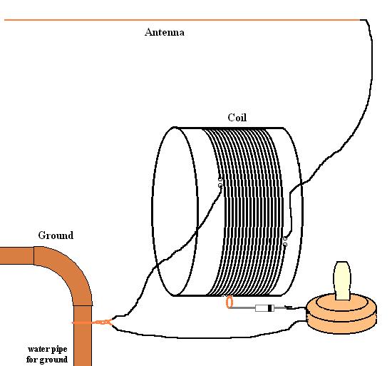
Figure
#4
A
small amount of the radio wave energy stored in the coil (our 610 kHz
or
610,000 cycles per second) moves to the detector or the device called a
diode.
The energy is an alternating current signal (AC) at this point. The
detector
(diode) rejects half of the alternating current signal and the signal
looks
like figure #5 below. Now the signal is a pulsating direct current (DC)
signal.
 Figure #5
Not discussed here is tuning the coil to get different frequencies.
That can be
done by adding more turns of wire around the coil form. Or removing
some. On a
simple radio, this is done by moving the diode up or down the taps on
the radio
in effect making the coil longer or shorter. This changes the
"inductance" of the coil or makes it resonant to different
frequencies.
Another way to do this is to add a variable capacitor across the coil.
This adds
or removes capacitance to the coil and changed the resonant frequency
the coil
will tune to.