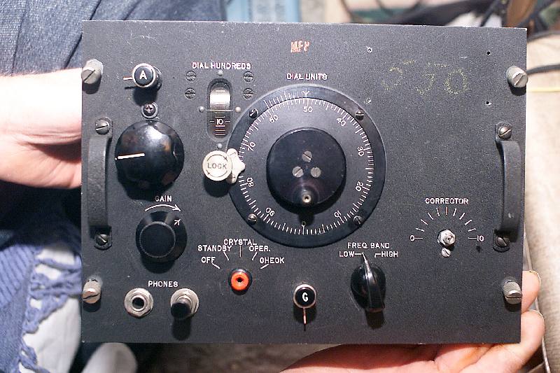
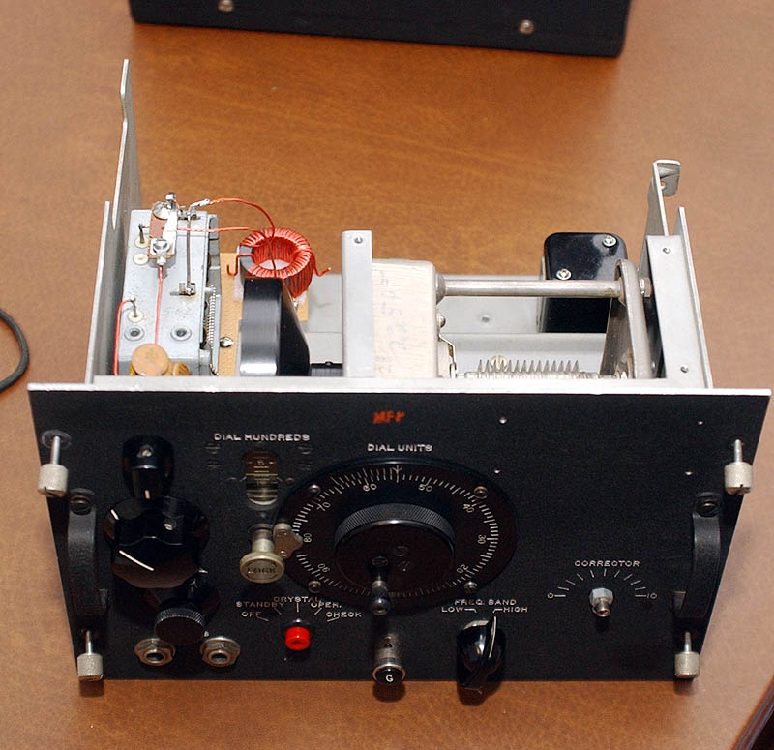
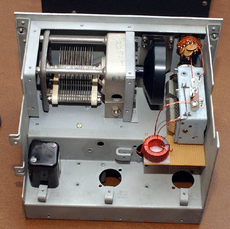
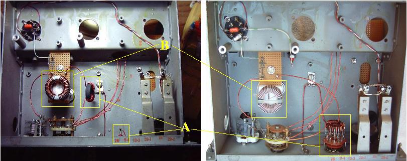
Crystal Radio
stay tuned crystal radio and tube radio website
crystal set


Designer/Builder Steve Bringhurst

tk2 crystal radio

Don't miss the revisions to set at the bottom of this page!

This is not intended as a "How To" article for a beginner. The following is supplied as information only. Some of the techniques used in the construction of this radio are very advanced and not recommended for a beginner or even an intermediate builder.
    

Please Click On The Photos To Enlarge Them


Photos Just After Construction

tk2 crystal radio 2
Front Panel of the TK-2

tk2 crystal radio 3tk2 crystal radio 4
Rear view (Left) and Bottom View (Right)


tk2 crystal radio schematic


Parts List

L-1       Antenna coil; FT-114A-61 core. 18 ga 
             individual-insulated 8 stranded 27+9 turns. 
             182uH full length/low range. 105uH to tap/hi 
             range.

L-2        Detector coil; FT-114A-61 core. 39 turns/205uH,
              18 ga 8 strand individual insulated.

            *Alternate Detector coil; Ft-114A-61 core 
              polystyrene slurry double-coated. 35 turns 
              Figure-8 wound 18 ga single conductor magnet 
              wire. (See changes below in the "Revision" 
              section) 210uH

T-1       Coupling transformer; FT-82-61 core. Primary 9
             turns/6.8 uH, secondary 7 turns/4.3uH 
             individual-insulated 8 stranded both.

T-2       UTC-A27 Audio Transformer
VC-1    500/440 pF Variable Capacitor
VC-2    28 - 225 pF Variable Capacitor
TC-1    5 - 25 pF Variable Capacitor 
D-1      Germanium Diode ITT FO 215
C-1       470 pF Capacitor
C-2       220 pF Capacitor
C-3       220 pF Capacitor
C-4       100 pF Capacitor
C-5       47 pF Capacitor
C-6       207 pF Capacitor
C-7       .33uF Capacitor
VR-1    1 meg ohm Variable Resistor
SW-1    6 Posision Ceramic Rotary Switch
SW-2    DPDT Ceramic Rotary Switch
NE-2    NE-2 Neon Lamp


Photos of Finished Unit


Revision 1

New Doped Core Dual Coil Figure-8 Detector Coil Installed

figure eight toroid coil

Alternate experimental detector coil; Ft-114A-61 core polystyrene slurry
double-coated. 35 turns Figure-8 wound 18 ga single conductor magnet wire.


Note: (from version 2)

The fig-8 windings & styrene coating were intended to reduce distributed capacitance thru the core.
The fig-8 is retained in version 2 and the coating not used as the litz allows spacing from the core & between turns.

Fig-8 winding puts the ends of the coil where max RF voltage occurs opposite on the core for max possible
distance giving lowest potential core leakage loss.


Revision 2

tk2 high performance crystal radio

See Photo above "A"

The major change is an adjustable coupler instead of the fixed one in the original. Ten tapped turns per side provide simultaneous tap-switching at 2,4, 6, 7 8 and 10 turns on both windings via a 2-pole /6 position rotary switch.

This allows control over sensitivity/loudness and some further control over selectivity used along with the antenna coupling adjustment.
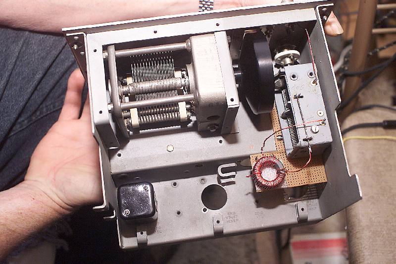
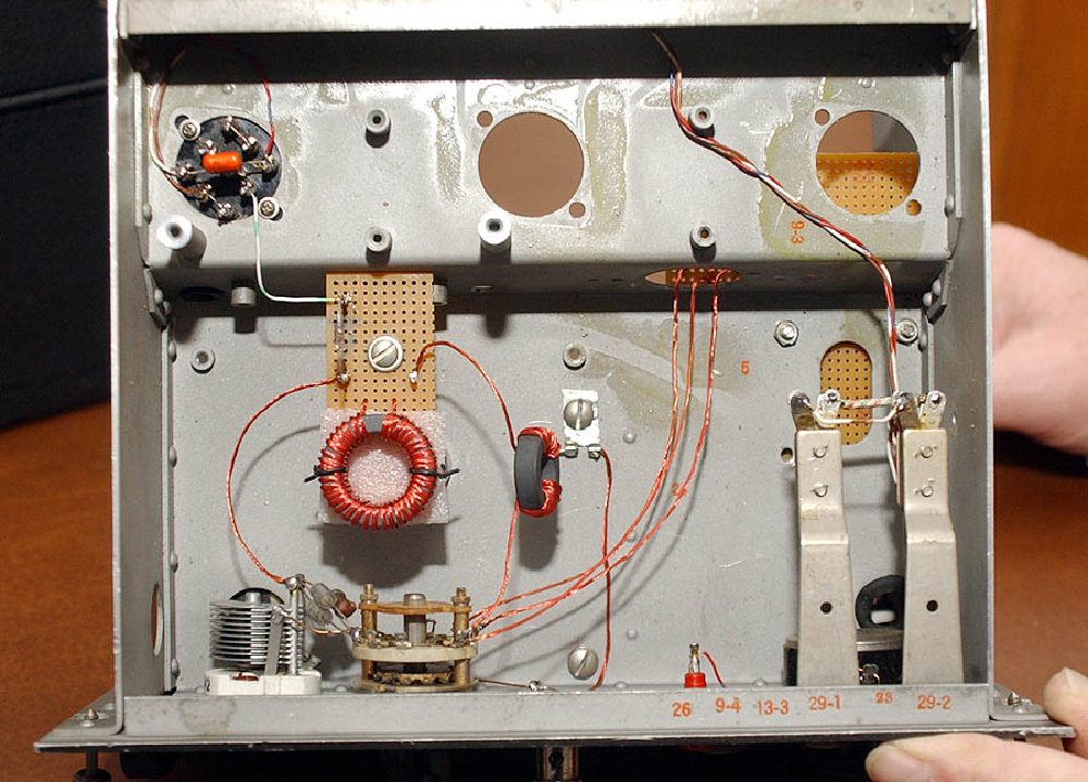
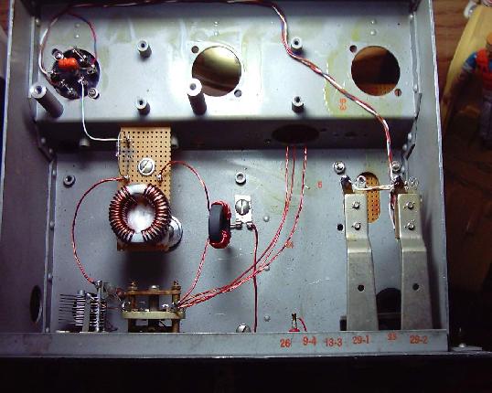
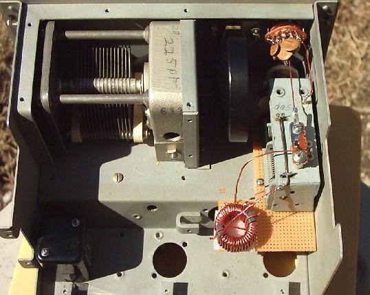

See Photo above "B"

Other detail changes include a 165/46 litz fig-8 wound detector coil, a mini- porcelain insulated terminal post for the "hot" side of the detector tank, and remounting the antenna and detector resonance coils on lo-loss styrofoam pads. All these changes further reduce distributed capacitance & leakage losses.
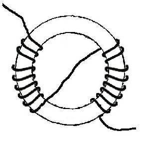

Notes:

12+12 turn 1st version of the coupler, tapped every other turn. I subsequently cut off 2 turns of each winding and re-ordered the tapswitching as previously outlined. The switch rotors are joined & grounded, clockwise switching increases the # of turns in-circuit and thus coupling factor.

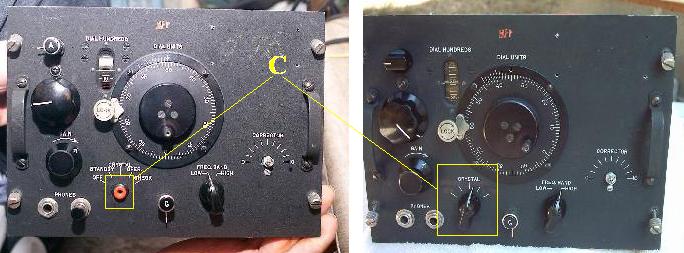
I've moved the metering jack to the center apron of the chassis to make the panel hole location available for the coupling unit.


tk2 crystal radio revision
(click on above photo for a larger view)


tk2 crystal radio front comparison

Front panel change (see photo above "C")
Moved the metering jack to the center apron of the chassis
to make the panel hole location available for the coupling unit.


tk2 high performance crystal radio
(click on above photo for a larger view)


Special Thanks to
Steve Bringhurst
For sharing this radio with us


Crystal Radio


Return to "Stay Tuned " Home Page


© 1999-2010  Darryl Boyd,  All rights reserved
Copyright Notice:
My website is copyrighted. This includes all images, text, drawings.
If you are thinking of downloading my copyrighted items and selling them on ebay (or anywhere) keep this in mind,
I monitor ebay for such violations.  I will pursue the issue with ebay and in the courts if necessary.
I do not furnish them for  your gain from my hard work.


Send Email To:


b o
y
d
@
b
o
y
d
h

o
u
s
e
.
c
o
m
Because of antispam techniques, you can not "cut and paste" the above text

We have made every effort to ensure that the information provided on this website is accurate and up to date.
All information on this website is informational only and no
guarantees to the accuracy of any of the projects
or circuits on this site or calculators. If you find something you feel is inaccurate, please inform us by e-mail. Be sure to provide a thorough argument to support your case. Confirmed changes will be made as quickly as possible.

The images on this website  are protected by copyright.  They are the property of the owner of this website and may not be used without the owners permission. Please don't use the images made by us on this website without