|
Introduction:
Being a crystal set ‘purist’ means, to me, no power
or amplifiers. I had to back off that stance with the Hawaii long
wave (LW) scene. Only three local LW
beacons could be heard --
one of those only at night. It’s well
known that a beat frequency oscillator’s (BFO) signal, when applied to
an
inaudible continuous wave (CW, code) signal, will make it audible. It’s perhaps less well known that the same
BFO applied to amplitude modulated (AM) signals, as used in the
broadcast band
(BCB), can greatly increase their strength and readability. This effect is ‘exalted carrier’ reception.
The BFO is nothing more than
a signal generator. As we shall see, it
can be a lot less. By loosely coupling the output of a small signal
generator
and tuning it to the frequency of the LW crystal set, many more LW
beacons were
heard.
Exalted Carrier Reception:
Crystal sets
by their nature are inefficient in detecting weak, distant (DX) signals. Tuning a BFO to the carrier of a weak DX
signal raises the voltage of the signal to a region of much
more efficient detection. Exalted carrier
is amplification of sorts, but it is
different from
regeneration or reflexing – here, the set is continuously in
oscillation. In the case of an isolated
weak DX signal,
exalted carrier raises the signal to the level of readability. When the weak DX signal is 'buried' by a
strong interfering (QRM) signal, exalted carrier selectively raises the
level
of the DX signal. The hope is, the DX
signal can be raised to a level at which the brain
can select the DX program in the presence of
the QRM program. There must be more high-powered explanations around,
but
that's the gist of it.
In a way, exalted carrier is
related to direct current (DC) biasing of the detector diode to get to
a more
efficient detection region. But exalted
carrier is radio-frequency (RF) ‘biasing’ of the detector at
a specific frequency – very important distinction.
Exalted carrier reception is
not new. Early on, hams discovered that
weak AM signals could be enhanced by tuning them in using the single
sideband
(SSB) mode. Here again a local
oscillator in the receiver is tuned to zero beat with the AM carrier. These rigs had the further advantage that you
could select the sideband (lower, upper) you want to listen to. Many of the older top-of-the-line
communications receivers, Hammarlund, National, etc., include it among
their
features.
Beat Frequency Oscillator (BFO):
My
original
BFO, a small EICO 330 solid state signal generator, served well to
bring in a
variety of distant LW beacons. In
late-2004/early-2005, a new One-Active Device (1-AD) contest to
complement the
Crystal Set DX contest was announced. Steve
McDonald suggested that I should try applying the
BFO idea to BCB
reception in the 1-AD contest.
Because of the 1-AD Contest
limit of one active device – 1 tube or 1 transistor -- I planned to
replace the
EICO with a simple, one-JFET Hartley BFO as "proof-of-concept" and
then to build from there. As it turned
out, there was little need to go beyond this basic one-JFET set.
The schematic and circuit
board pictorial of this textbook BFO are shown below.
The BFO is connected to the
crystal set by attaching a clip lead to the OUT post and loosely
wrapping the
lead around the crystal set’s antenna lead-in wire.
The BFO and crystal set grounds are not
connected. The coil and tuning capacitor
should be high
Q to keep the oscillations sharp as possible.
The BFO is very
frequency-stable in the short term in spite of there being no supply
voltage
regulation provisions. I planned to
address voltage regulation in Phase II, but never got that far. 'Warm-up time' is 10 to 15 seconds. I can tune in a station, turn off the BFO for
an hour or so, then turn the set back on to hear a high-pitched whistle
descend
exactly to zero beat in a matter of seconds. One
thing working for frequency stability is the low
current draw, only
about 0.3 mA.
Now, let’s look at this BFO
applied to long wave and BCB crystal sets.
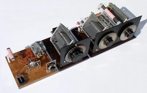
Long
Wave (LW) BFO Receiver
At left is the 1-MPF 102 JFET
BFO. In center is a 1000 pF variable
capacitor shunted across the BFO's tuning capacitor to get to low
frequencies. (The BFO was originally
designed to cover the BCB.) The two-dial
unit to the right is a double-tuned LF crystal set.
Also used but not shown are sound powered
phones and matching transformer. A clip
lead from the BFO output is wrapped around the crystal set's antenna
lead-in
for injection. The BFO provides exalted
carrier for AM signal reception or an audible beat note for CW
reception. The complete circuit is shown
below:
The crystal set itself is a
series-tuned front-end loosely coupled to a parallel-tuned secondary
detector
section. Of several designs I tried,
this one seemed to work best. This set
has received over 80 LW beacons covering the Pacific area, from Samoa
to the
Aleutians, west to Japan
and well into the mid-western states. The
most distant is beacon DDP in San
Juan, Puerto Rico at 5850
miles. DDP is
notable for its wide coverage.
In mid-winter months when
propagation is best, ‘local’
beacon LLD, 70 miles away on the island of Lana`i, provides a very
powerful
signal and carrier. In fact, so powerful
LLD’s carrier itself can exalt the signals of beacons nearby in
frequency. Stations heard with the local
BFO turned off
include ones in British Columbia, Alaska, Montana
and the Cook Islands.
All
it takes is some careful listening in the silent spaces between the
loud LLD
idents. In essence this is crystal set
operation with a remote BFO – 70 miles remote! This
effect is much more prevalent on the mainland where
there is likely
to be a much higher density of strong local beacons.
At my former Maryland
location, I never thought to use an
amplifier or a BFO.
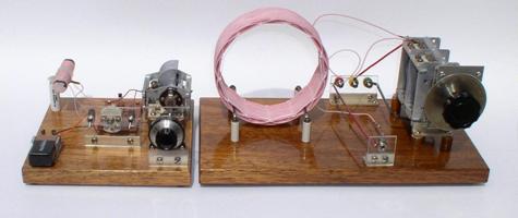
Medium
Wave
(MW)/BCB BFO Receiver
The one-MPF 102 JFET BFO is
loosely coupled to a modified MRL #39 ® single-tuned crystal set.
The BFO is at left. Again,
matching transformer and sound powered
phones are not shown. The BFO is coupled
to the MRL #39 ® by wrapping a few turns of a clip lead
from its output
around the
antenna lead-in. The circuit is shown
below.
Performance:
An
indicator of the sensitivity of this set
is the ring in the phones when either BFO or MRL #39 ®
tuning capacitor is
lightly
rapped, causing the plates to vibrate. This
is classic frequency modulation about the zero beat.
Equally significant is greatly enhanced
selectivity -- so much so a wave trap is rarely needed.
There is
splatter on the baddest actors, but that's the station, not the set.
The strongest
(non-splattering) local stations were noted to 'pervade' the spectrum
several
tens of kilohertz to either side of their center frequencies. This is because the MRL #39 ®
set, good as it
is, has only so much selectivity. You
can tell when an off-channel local is present because its audio quality
is not affected by re-adjusting the
BFO. As described below, on-channel
audio quality is greatly affected by
tweaking the BFO exactly to its frequency.
No set is perfect.
Here
are some drawbacks:
The simple BFO does have
harmonic content. The BFO is going to
exalt strong signals at 2x, 3x, 4x, etc. the frequency you're tuned to. For me, this means local stations at 1080,
1500 and 1540 show up at 540, 750 and 770 kHz and make listening to
these
frequencies difficult. 2.5 MHz WWVH ties
up 1250 kHz -- I also hear them on 625 kHz. A
far greater threat – especially for the MRL 39 set -- is
all the short
wave (SW) going on, especially in the evening. Fortunately,
my location is in the SW boonies.
A spotter radio is
near-useless -- dead as a doornail. Front-end
overload by the BFO signal causes automatic gain
control (AGC)
clamping in the spotter. Turning the BFO
off brings the spotter back to life. But
you can't listen to both simultaneously to verify identical program
content. It's not that difficult without
the spotter. Tune to a known station and
'count channels' to either side by noting the ascending/descending
pitch squeal
to the next zero beat. The ideal spotter
would be a digital readout radio whose AGC can be disarmed.
The BFO requires some deft
tuning to get exact zero beat. At the
top end, this is nearly impossible -- so I tune as close as I can and then zero-beat by judiciously
positioning my left hand near the BFO -- a hand capacitance vernier. Because BFO tuning is so touchy, I chose
the MRL #39 ® single-dial crystal set over the
two-dial Lyonodyne-17. Even when the
carrier is zero-beat the audio
is degraded because the modulation sidebands are off-frequency. Speech sounds like SSB 'duck talk,' and music
can get trashed beyond recognition. But
we're talking DX here, not hi-fi, easy music listening from the Lazy
Boy.
I discovered that frequency
stability does suffer over the very long term as the battery supply
decays. On the last night of the 1-AD
Contest, I switched out of desperation to a new battery.
(The old one had been in continuous evening
use for almost four months.) With the
new battery, BFO calibration points were shifted by a small but
noticeable
half-percent or so.
Future
Improvements:
Top of the line Fair Radio
500 pF capacitor. May need to reduce the
inductance of the coil a little to spread the band out.
Improved vernier dial -- something
larger, perhaps even a double vernier drive.
Variable level injection --
through an actual var. cap. instead of the gimmick.
Harmonic
suppression --
low-pass filter, or tuned parallel tank as a notch filter.
At the same time I don't want to shoot myself
in the foot by attenuating high-end BCB BFO output.
Conclusion:
To folks
considering trying
this idea, I’d suggest, Don’t build anything at first – try out a
signal
generator ‘BFO’ on one of your own crystal sets. Remember
to keep the generator output low and
the coupling to the set as loose as possible. It
doesn’t take much at all. If
performance seems promising after several evenings of listening, e.g.,
SW is not
a problem, then consider a ‘dedicated’ BFO such as described above.
I’m convinced that part of
the impressive performance of these BFO’ed crystal sets is due simply
to the
crystal set itself. A well designed and
constructed crystal set has outstanding qualities – among them,
sensitivity, selectivity,
low noise – desirable in the front-end of any
radio set. We all know from experience
that crystal sets, by themselves, can ‘hold their own’ with the big
rigs.
I think the advantage
of
exalted carrier over other forms of amplification (regeneration,
reflexing,
etc.) is that the amplification is applied to a selected frequency.
While a
tuned RF amplifier may come close, it’s hard to imagine a more
effective use of
a single active device to improve crystal set performance than by
exalting the
carrier with a simple BFO.
|