Macrohenry's Crystal Radio for Casual Listening
For more information see Tom's web site at http://www.tompolk.com/crystalradios/Homebuilt/crystalradio.html
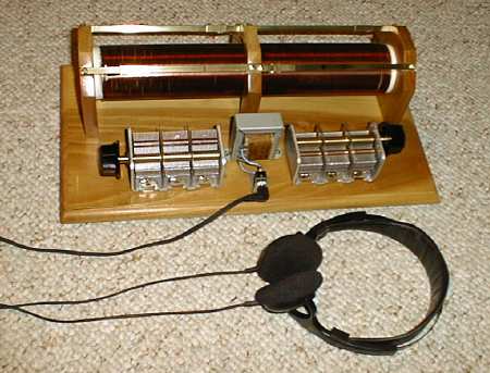
Having been inspired by the building contest, I built this radio in January and February 2001 for use in my workroom. This is a crystal radio, using no outside power or batteries. It derives its power from an outside antenna strung across the roof of my house. It is quite sensitive, and it's efficient enough to drive a speaker directly from the earphone jack (that's right, no amplifier), which never fails to astound me. With Walkman-style headphones, the fidelity is awesome, rivaling FM. Who would think AM could sound so good!
The radio
is not the only thing that must be sensitive. I must be, too.
Because my workroom is visible from the kitchen and living room, it's imperative
that I include the SAF (Spousal Acceptance Factor) into my design specifications.
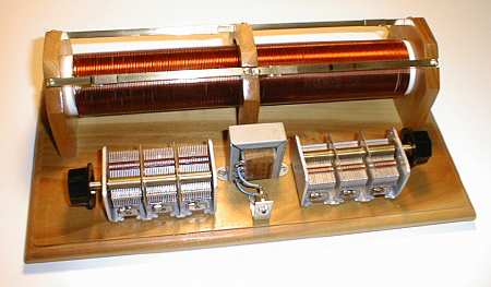
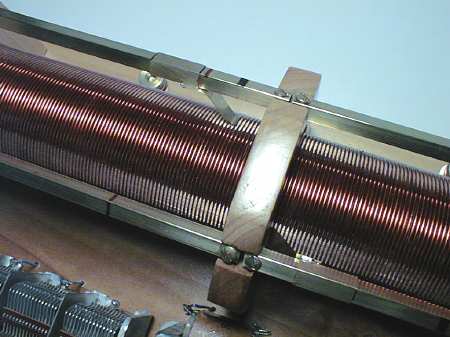
I chose to use all new parts in this project. The wood is poplar,
browned in the sun, covered in two coats of laquer, sanded and finished
with paste wax. You can glimpse a hint of its beauty in the images.
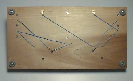
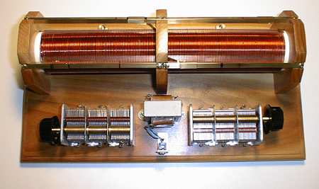
Barely visible at the bottom left and center are blue wires emerging from holes in the wood where they are soldered to the variable capacitor and the transformer. Visible toward the top left is the brass knurled knob for the antenna connection.
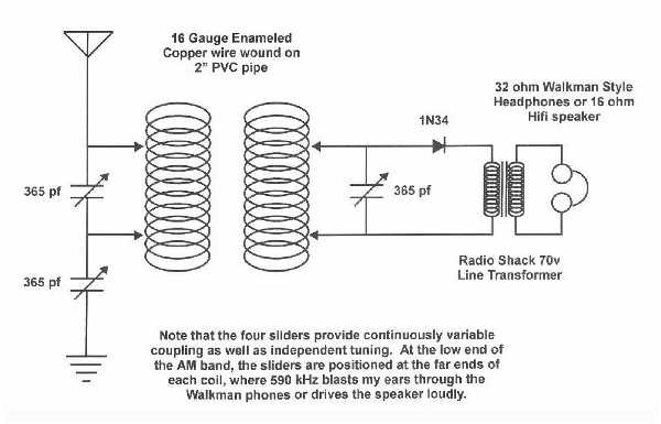
Schematic