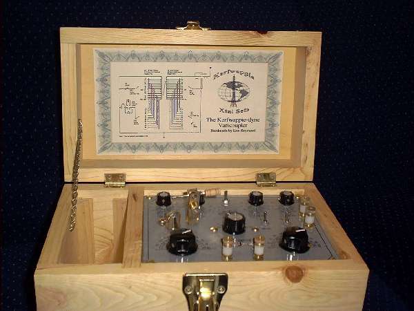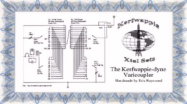
The Kerfwappie-dyne Varicoupler
Built by Eric Raymond (aka Raysistor) ĀĀĀĀĀĀĀĀĀĀĀĀĀĀĀĀĀĀĀ February 27,2001
bluherron@earthlink.net
General Building Category / Master Class
Design
Being fairly new to this hobby, I tend to spend a lot of time looking at old radios on Ebay.Ā I get a ton of ideas by looking at what others have done.Ā This is theĀ second radio I have built.Ā The first being a loose coupler that I didn't completely finish.ĀĀ I am a plumber by trade.ĀĀ One day at work I got to playing around with a few scrap pieces of ABS drain pipe, cutting them down so that they would fit together like the varicouplers I'd seen on Ebay.Ā At this point the gears started to turn and I began putting it together in my head.Ā I started thinking about certain things I needed this radio to do.Ā I wanted to be able to increase or decrease the size of the coil in order to reach both ends of the band.Ā Ā I also needed to vary the taps where the antenna and detector connected to the coils for easy impedance matching.Ā Having never before heard or seen a radio that actually used a catwhisker and crystal, I had to have one of those and I would need a buzzer to help tickle the crystal.ĀĀ I also wanted to be able to experiment with different diodes and such.Ā This radio needed to be portable too.Ā I wanted to be able to take it with me on trips without to much trouble.
Construction
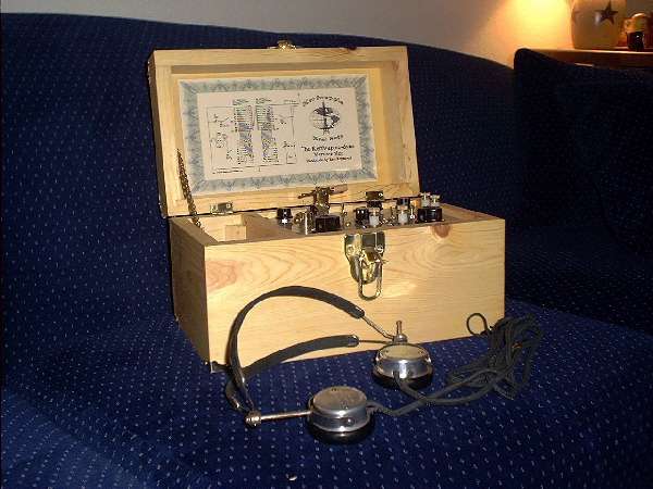
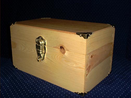
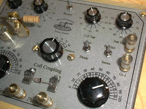
I started with the box.Ā I built it out of a few pine 1x10 boards that I snagged out of the scrap pile at one of my jobsites.Ā I cleaned them up, sanded them smooth, and went to work routering the dovetail joints and dados.Ā I used straight grain fir veneer for the top and bottom, these were also scraps from work.Ā After a little glue, some more sanding, and a coat of Watco oil, I was ready to put on the hardware.Ā I chose some brass corners, a couple brass hinges and finished it off with a brass toggle hasp. With that done, IĀ started acquiring all the nuts, washers and screws, as well as, the knobs and switches.Ā I bought most of this stuff from the local hardware store with a few parts from Radio Shack .Ā While I gathered the parts to together,Ā I started arranging the layout of the radio.Ā Using my computer and a few different graphics programs,Ā I put together a template with scales and labels for the various switches, knobs, and binding posts.Ā At this point I will admit to shamelessly lifting the two capacitor scales from one of Mike Peebles project layouts featured in The Xtal Set Society Newsletter.Ā Thanks Mike
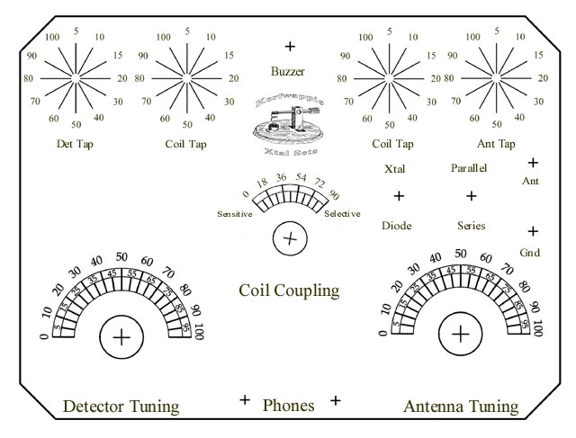
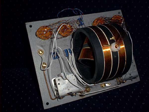
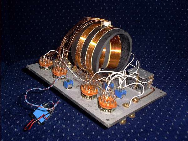
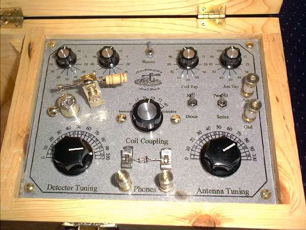
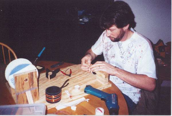
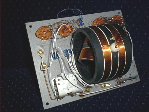
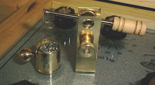
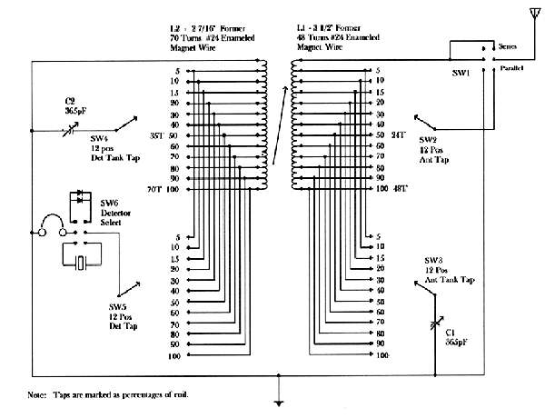
After getting the layout the way I wanted and making sure all the parts fit, I then printed this out on a piece of grey heavy bond parchment type paper and glued it to a piece of 1/8" Plexiglas using a spray on adhesive.Ā After the glue had dried, I then sealed the paper with a spray fixative to prevent the paper from absorbing moisture.Ā This was a trick learned the second time around.Ā I didn't do this the first time and the moisture caused the paper to delaminate after I had all the parts in place.Ā At this point I drilled all the holes for the various shafts and screws and started to assemble them.Ā The coils are wrapped onĀ 2" and 3" ABS pipe.Ā L1, the antenna coil, consists of 48 turns of #24 enameled magnet wire around a 3 1/2" former.Ā L2, the detector coil, consists of 70 turns of #24 enameled magnet wire.Ā Both coils are tapped at 5,10,15,20,30,40....100% of the coil.Ā I started out by cutting the pipe/formers to size on my chop saw.Ā Using my drill press, I then drilled the holes for the shaft to fit through and test assembled the two forms together, making sure the inner form was free to turn all the way around without touching the outer former.Ā After making sure that everything fit, I marked and measured for the wire.Ā I wrapped a layer of double back tape around the form where the wire was to be.Ā This helped to hold the wire in place while wrapping.Ā I made a jig in order to hold the wire spool with a constant amount of tension and a clamp to hold the form when my hands went numb.Ā I would wrap the wire, solder a tap to it and continue wrapping.ĀĀ After the coils were wrapped, I assembled the two of them together using a thick hollow plastic straw that I acquired from a Popsickle treat.Ā It is 1/4" diameter and fit my Radio Shack tuning knobs perfect, and besides that, being plastic is better for the coils.Ā On the inner coil I pulled all the taps through the form to the inside, where I ran them through a hole in the side of the straw and out the end of the straw.Ā I then secured the inner form to the straw with super glue and used two plastic shaft collars to align and hold the shaft in place.Ā At this point I drilled and tapped holes for mounting the Varicoupler to the radio board, and attaching stops to the shaft collars in order to maintain 0-90 degrees of movement.Ā I mounted the rest of the switches and the two 365pF air variable capacitors.Ā I purchased these online from The Xtal Set Society.Ā The binding posts are brass #8 screws with two knurled nuts and a nylon spacer.Ā Having all the main components mounted, the only thing left to do was to fire up the solder iron and wire it up.Ā I used silver plated Teflon insulated hook up wire for most of it.Ā The taps are #24 enameled magnet wire.Ā I threw together a buzzer circuit using a 9v battery and a relay to help with finding the spot on the crystal.Ā With everything done under the hood, I turned it over and put it in the box.Ā Next came the detector.Ā I made the detector stand out of a piece of brass flat bar.Ā I cut it to size and bent it up on a small brake.Ā I then slid it over a block of wood and drilled the holes using my drill press.ĀĀ I made the arm by taking 1/4" - 20 brass screw and turning it in my drill press, using a file to takeĀ off the threads and shape it.Ā I then followed up with different grades of sand paper, finishing with 1500 grit.Ā The balls are lamp finials.Ā The cup is a 1/2" brass sweat plug from a tub/shower valve.Ā The whisker is a phosphor bronze wire, unwound from my buddies old guitar string.Ā The handle is a dowel that I turned in my drill press.Ā I am using is a piece of pyrite that I potted into solder using a wooden mold.ĀĀ I also mounted a set of Fahnestock clips to hold a diode for the times when you want to experiment with different diodes or don't want to fuss with the crystal.
The Circuit
Performance
The performance of this set was not what I had anticipated.Ā It is about as sensitive as a Marine Drill Instructor.Ā It exhibits good selectivity and covers a good part of the band, between 570khz -1300khz.Ā It gets all of the local stations, and with 300 foot antenna they are quite loud.ĀĀ